Consider this page a work in progress. Once he has more free time, Trip will be posting pictures and telling stories about all the upgrades made to Kalyra through the years.
(a few weeks later…………)
Trip here. As we all know, you find the perfect boat, you buy it, then you spend the rest of your ownership making the perfect boat perfect. We were no exception (although Nicole has said several times that I may be more fanatical – read “nuts” – than most).
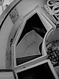
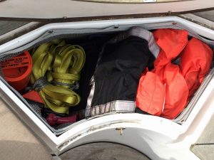
LAZARETTE: I’m all about access, so when I couldn’t get to the aft end of the hull for the exhaust pipe, rudder post & quadrant because of an athwartship Ubeam that supported the Autohelm, I cut out the starboard, aft lazarette. I replaced it with a plywood bottom mesh bag that can be unsnapped & removed, allowing me to climb down. An added bonus is that the bag has twice the capacity as the FG lazarette.
STERN: These pictures show several projects –
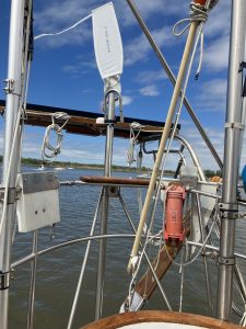
We extended the davits up two feet & reinforced them. We added a 140W solar panel & a Rutland wind generator to keep our batteries charged without running the engine. We installed a GPS smart antenna (the little white dot centered in front of the solar panel) which sends position & time to both radios.
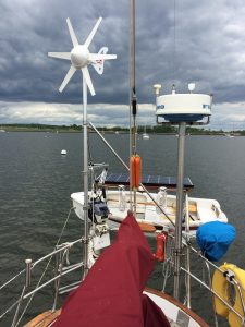
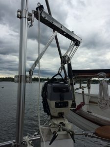
And we installed a crane for our outboard (which Nicole refers to as “the marriage saver”).
NAV DESK: When we got the boat, the instrument panel consisted of a fused toggle-switch subpanel, an 8” tall piece of teak with flush mounted Datamarine Link 5000 (depth, knotmeter, wind direction & speed) & a flush mounted Loran. The area above this was a shelf, together with a bracket-hung VHF radio. There was also a Lat/Long GPS on a swing-out bracket above that could be seen by the helmsman.
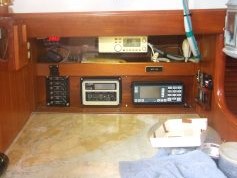
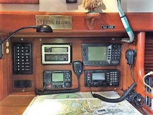
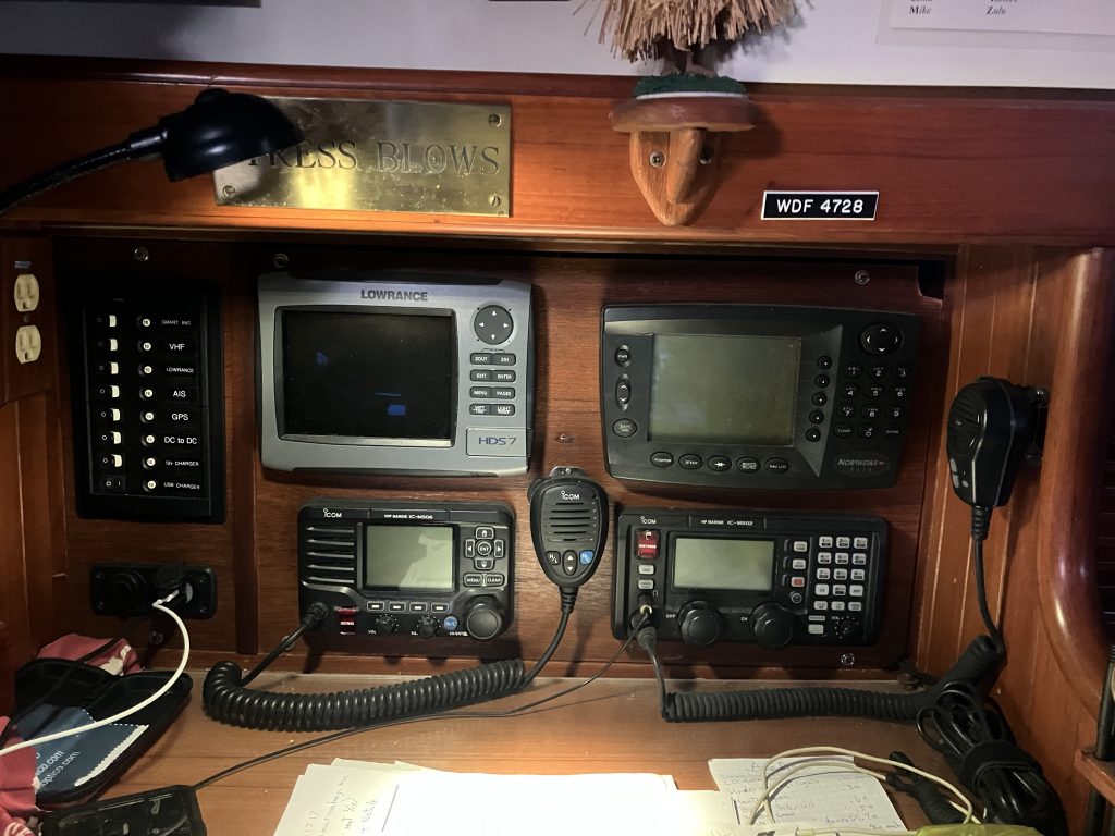
I removed everything from the instrument area, reworked the wiring & installed new, heat shrink connectors and added a new buss bar for all the negative wires. I then fabricated a two piece teak panel that would cover the entire opening. I flush mounted a new, 8-position, circuit breaker subpanel, the Datamarine (old but still reliable), the Lat/Long GPS (from the swing-out bracket), an Icom SSB radio for long range communication & a new Icom VHF radio (the old VHF radio was excellent but there was no cockpit remote available for it & as we didn’t want to go down in the cabin every time we needed the radio we bought a new one). On the swing-out bracket I installed a chartplotter. I’d also installed an AIS (automatic identification system) that displays other vessels on the chartplotter screen. Very nice knowing the location & names of the vessels around you. The circuit breaker subpanel has a switch for: A Smart Antenna which sends position & time to the two radios, the VHF radio, the Datamarine, the AIS, the Lat/Long GPS, a DC to DC regulator (which I installed to produce a constant voltage to a laptop regardless of the voltage fluctuations of the house batteries), a 12 volt charger receptacle & a dual USB charger receptacle. The large desk is a good working area for charts and the white/red gooseneck LED chart light is a great help.
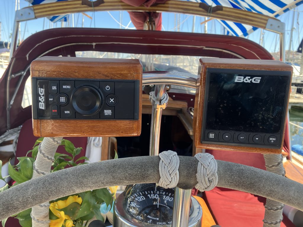
UPDATE: We installed a NMEA 2000 system, replaced the swing-out chartplotter with a Zeus3 (installed the Lowrance at the nav desk where the Datamarine was), installed B&G wind, depth, temperature & speed transducers. We eliminated the Datamarine remote at the helm & replaced it with a ZC3 controller (for the chartplotter) & a Triton2 that can display depth, speed, wind, temperature, tide, etc, etc. We also installed a B&G Halo radar (replacing our old analog Furuno) which displays on the chartplotter.
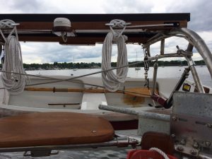
TRAVELER: Kalyra had the original “knuckle buster” traveler for the main sheet. You had to hold the main sheet car, pull up the pin on the stop, slide the stop down the track to where you wanted it, then release the car to let it slide (read “crash”) against the stop. Being innovative (read “cheap”), I removed the pins from the stops & drilled & tapped the track so that the stops would prevent the car from hitting the ends of the track. I then attached two, double block control ends with cam cleats to each end of the track. I bolted a 1/4” rectangular piece of stainless steel to the top of the car which holds two, double sheave blocks. With a line going through both sets of blocks on either side & then through the dodger, we can now adjust the angle of the main sail from the cockpit. (PS, that was the old dodger in the picture).
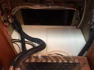
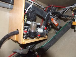
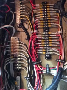
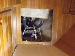
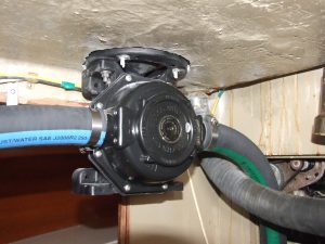
ELECTRICAL PANEL & PUMPS: Though we’d had the boat for a few years, two things drove me nuts. The water, bilge & sump pumps were all located on a shelf behind the electrical panel (and which was above the engine), and all the wiring (DC & AC) was connected to a 20” terminal strip with little #8 screws (including the big 2/0 negative cable from the engine!). Jumpers were placed on the strip to turn part of the strip into a buss bar where needed, additional wires went over the pumps, & not a single wire was labeled.
I eliminated the sump pump (another posting further down), I relocated the bilge pump under the big shelf in the starboard lazarette, & I relocated the water pump under the galley sink. This eliminated lots of hosing & most importantly got the pumps away from the electrical panel and the engine.
As to the wiring, once I had a plan, I installed a DC positive terminal strip, a DC negative buss bar, an AC terminal strip & a grounding buss bar. All wires were labeled (I love that P-Touch labeler) & the labels were protected by clear, heat shrink tubing. I also doubled the positive feed going into the panel as the original feed was borderline. I made a new & easily removable shelf. What a relief knowing at a glance where wires go.
LIGHTING: To reduce electrical consumption, we changed all the main interior & exterior lights to LEDs. All the interior dome lights were refitted with LED “bulbs”. We had also installed three, LED undercabinet lights over the galley countertop (these can be switched to either white or red). The exterior bow & stern navigation lights & the steaming light were replaced with the much brighter & more efficient LED units. We also replaced the very large, incandescent trilight/anchor light at the top of the mast with a small LED unit that also is brighter & more efficient. Aside from using this at times when not using the bow & stern lights (much better to use a trilight when offshore), this trilight also has a strobe feature if needed & a photocell for the anchor light. We turn this on whenever we anchor, then we don’t have to worry about getting back to the boat before dark, I don’t have to worry about forgetting to turn the anchor light on, and, most importantly, I don’t have to think about getting out of a comfy berth when the sun comes up & the anchor light should be off.
VANITY & SUMP PUMP: Did I mention access? Though there were three seacocks inside the vanity together with hoses for the sink & toilet (with a valve to switch from flushing overboard to flushing to the holding tank), all this could only be accessed by sticking your head & one arm through that little louvered door. I cut out the front of the vanity, glued teak trim to it & used pins & turn locks to hold it in place. Now I have full access to everything within the vanity & without having to go through major contortions.
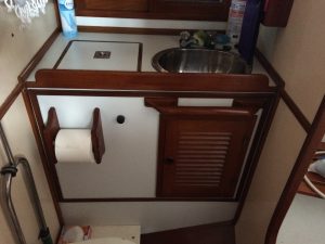
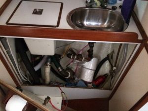
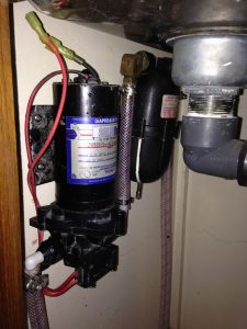
We had replaced the toilet hoses & installed a Y valve to direct the flushing to either holding tank or overboard. I’d also installed a new sump pump that bypasses the grey water tank (now a great storage area) & is “Y’d” into the sink drain. The drain area for the shower holds water from several showers, then pressing a momentary switch activates the pump.
FORWARD CABIN (our cabin):
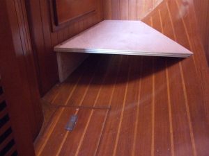
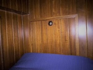
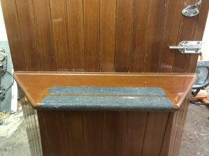
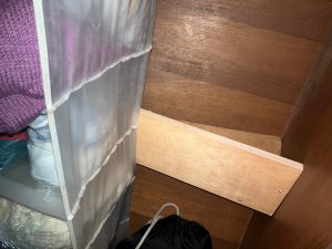
Two things were (for us) a problem with this cabin. First, because our cabin is a pullman style with the berth running along the port side (rather than a V berth that fills the whole space between port & starboard), whenever you got out of bed you were stepping on a curved floor because of the shape of the hull. Under normal (?) circumstances this is a disconcerting problem. When you have been celebrating too much (ie: a nice sail, a snug anchorage, today is Tuesday, etc.) this can be disastrous. To solve this problem, I scribed & cut a piece of plywood as a flat, large step about 4” above the bottom of the curved floor. I scribed & cut a second piece of plywood which was a support for the left end of the step. To finish this off, I scribed a piece of teak as the face & covered the step with carpeting.
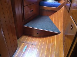
Now when you get out of bed you have a nice flat step to land on. You also have a level platform for getting dressed or for seeing how gorgeous you are when looking in the mirror. The 4” added height also helps in a big way when getting our spinnaker or folding bikes out of the storage areas under our bunks which brings me to the second change I made.
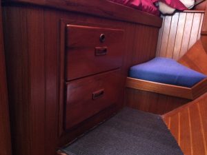
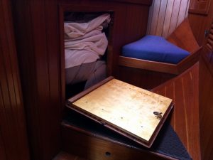
Though there were storage areas under the forward berth, two drawers made the largest area almost useless. I eliminated the drawers but kept the drawer faces. I cut the middle rail (that separated the drawers), then I mounted the two faces & the rail onto a piece of plywood. I installed hinges on the bottom of the plywood & a teak finger hole with a trigger catch on the top. With the exception of the finger hole, it still looks like we have two drawers under our berth, but this is actually a door that allows access to small items. This now gave us another large storage area where we keep our spinnaker (very handy as we launch & douse it through the forward hatch). Two folding bikes, boat screens, bags, etc. are in the more forward storage area.
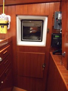
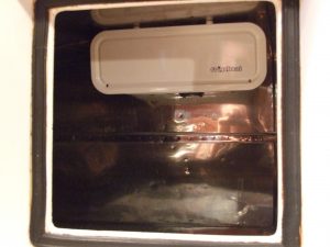
FRIDGE: We have two, front loading, stainless steel lined, ice boxes. The upper one is over 6 cubic ft. The lower one is over 5 cubic ft. When we purchased the boat, it had an engine driven fridge in the upper box. The problem with these units is that the engine has to be run for an hour in the morning & an hour at the end of the day. We wanted a 12 volt system that could be left on 24/7. After much research, we got a Frigobot unit with a keel cooler & an evaporator that’s horizontal with a door so it is a freezer as well as the cooling unit. No parts connected to the engine, which makes working on the engine much simpler, & a very small compressor which can go almost anywhere. I made a hanging shelf for mounting the compressor under the large shelf in the starboard lazarette. This was a “dead” space & it was also right behind the icebox & right above where I was going to mount the keel cooler. When I first turned it on I thought that something was wrong because I heard nothing. Only when I climbed down into the lazarette could I hear the compressor humming – it’s that quiet.

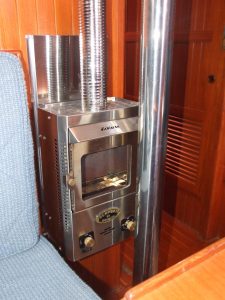
HEATER: Since we sail into November, we have experienced lots of cold days & colder nights. As we’re not in the Pacific Northwest, however, & we have no intention of sailing in the high latitudes, we just needed a heater that was simple & would keep us comfortable in the areas where we do sail. The Dickinson Newport P12000 propane fireplace heater was it. Centrally located in the boat, it keeps the cabin warm & the fireplace is so inviting (everybody sing!). There is an electric fan to blow the heat around & a double pipe chimney that draws & exhausts air from outside the boat to prevent condensation (which was a problem with the older propane heaters). The biggest installation issue was nerves – I had to drill a 3” hole in the cabin roof for the chimney. The expression for carpenters is “measure twice, cut once”. I think I measured at least a dozen times. It’s a scary thing to cut a hole in your boat, but it was definitely worth it. Very cozy.
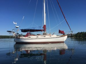
AWNING: This was given to us by a good friend of ours. Though made for a different boat, with some minor modifications & the addition of sewn-in loops for tent poles (to hold the awning open), this has been a great addition to our boat. It provides wonderful shade, we can sit in the cockpit when it’s raining & there’s even zip-on side & back flaps when the sun gets too low. Nicole says the colour reminds her of the French Riviera. Very nice! I recut our old awning to fit over the forward hatch where it allows a breeze in but not rain.
ACCESS: Again, did I mention access? There is a cockpit drain seacock on the port side that (also because of the athwartship support for the autohelm) could not be reached. So at the foot of the aft cabin, I cut an opening in the bulkhead. Installing trim & a finger hole on the cutout & fitting pins & a trigger latch, we now have full access to that part of the boat for the seacock as well as wiring, rubrail bolts, etc.
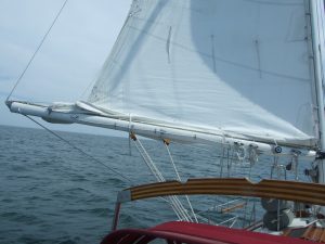
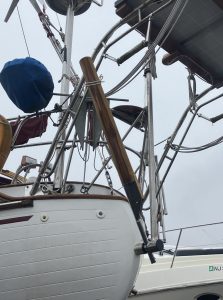
PREVENTER: There had been a boom brake (to slow the boom during a gybe) & a rigid boom vang fitted on the boom. Both items were going to be in the way of storing the dinghy behind the mast for offshore runs. Personally, I don’t like either anyway: The boom brake has lines going athwartship to both sides of the boat which have to be negotiated when going forward. I’ve also never liked attaching vangs of any sort between this spot on the boom & at the bottom of the mast as this is, at most, a 45 deg. angle of pull down on the mainsail – a very poor angle for tightening the leach. Back to the preventer: This serves two main purposes: 1) To prevent an accidental gybe (which can wreak havoc on your nerves, gooseneck [fitting between the boom & mast], mainsheet rigging, can knock a crewman overboard, or even kill). Needless to say, these situations need to be prevented.
2) To stabilize the boom by pulling forward & down while the mainsheet pulls aft & down.
To this end, I installed a bail at the outer end of the boom to which I’d eyespliced a length of line approx. ¾ of the length of the boom. At the other end of the line I also put in an eyesplice. On the side of the boom I’d installed a cleat about 6” more forward than the end of the preventer line. To this I eyespliced a short piece of light line which can be threaded through the end of the preventer line & cleated when the preventer is not being used. On the port & starboard caprails & even with the mast, I installed two padeyes.
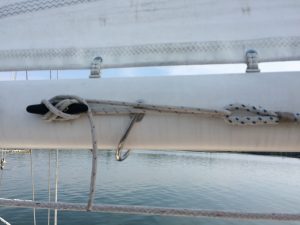
When deployed, I attach the control line end of a soft vang (came with the boat as part of the boom brake system – I had removed the cam cleat so this became a fiddle block, block & tackle) to the padeye & the other end of the soft vang to the preventer line. The control line is then brought back to a cleat near the cockpit for adjusting as needed. An added bonus is that this does pull down on the leech of the mainsail somewhat (I no longer race, so it pulls down enough, though a snatch block on the preventer with a line that goes down to the double-line fairlead on the caprail track would put more tension in the leech if needed).
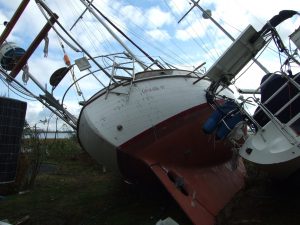
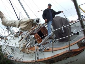
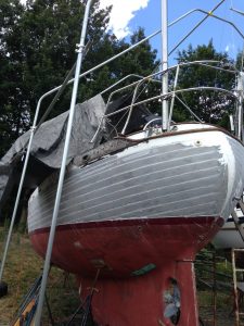
SUPERSTORM SANDY: Though we had experienced hurricane strength winds before & we had prepped the boat on our mooring as we monitored Sandy coming up the coast, nothing we did prepared us for the effect of this storm. As it had made landfall just south of our harbor, we waited for two days to check on Kalyra to give the emergency crews time to get organized. The morning that we were getting ready to head to the harbor, we got a call from a friend who was looking for his own boat. He had found Kalyra & she was not in the water. When we got to the scene, it was surreal. Boats in the streets, boats on top of cars, boats on top of other boats, boats wedged into buildings.
All this on a beautiful day. Kalyra was a mess & our hearts sank, but we reminded ourselves that we were still alive & we hadn’t lost a home unlike lots of people during this storm.
Much of the stainless steel hardware was destroyed or bent; all the port stanchions, the mast pulpit, the boom gallow supports, a dorade vent guard, the bow & stern pulpits, the dodger frame, the dinghy davits, the swim ladder, the cap on the rubrails. Also much of the external teak was destroyed; both rubrails, the port caprail, the 15′ port handrail, the boom gallows, part of the eyebrow, a dorade box, the three thick brackets that are fitted into the bowsprit & support the bow pulpit, part of the butterfly hatch. The port lifelines had been cut, the standing rigging had been compromised, the solar panel was smashed. Something hit our deck & was disintegrated but created a hole which allowed water to soak all the manuals, books & log that were on a shelf underneath. Some of the cabinetry & teak trim down in the cabin was cracked or had come loose. The white gelcoat of the topsides was severely scratched up. In short, she was a mess.
We have to say that the residents of this area of Staten Island were wonderful. They let it be known that we could use their bathrooms, their outlets for charging phones & even their couches to take a rest.
Once we settled with the insurance company (they considered it a total loss), we had the boat trucked over to Morgan Marina. This is where we winter the boat, it’s only 40 minutes from home, you have 24 hour access, there are lots of services & the people are great.
It took us 1 ½ years of constant work to restore Kalyra.
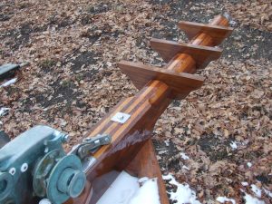

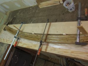
I had fabricated a new boom gallows (alternating teak & white oak strips), a teak dorade box, an 8′ section of eyebrow, three teak brackets (to be attached to the bowsprit & that support the bow pulpit platform), & parts for our butterfly hatch. Our garage & barn was filled with teak being fabricated, sanded & varnished before installation.
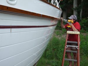
Rigging Only supplied the replacement standing rigging & lifelines. Joel & his team from Fiberdex stripped and regelcoated the topsides & recoated the deck (after we removed all deck hardware).
Stainless steel fabricators repaired the davits, bow & stern pulpits, gallow supports, and a vent.
The yard that built the boat, TaYang Yacht Building in Taiwan, was particularly helpful. Led by their wonderful employee, Wilson, they had all the templates for our boat. Via email, he was able to send me drawings of the stainless steel (stanchions, swim ladder, dorade guard, & mast pulpit) & the teak pieces that we needed (handrail, caprail & rubrail) with confirmation of all dimensions.
The fabrication of these were beautiful. The finished teak with air freight cost me as much as if I had bought the raw teak here, which would then have to be scribed, milled, etc. This saved us a lot of time.
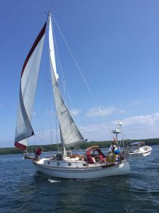
While down, we also stripped all hardware off the mast & boom, repainted them & rerigged them. I also made a new dodger (after rebending the old frame), a new binnacle cover, a new bow bag for the staysail & a new mainsail cover as the old one was too small for our new mainsail that we got in 2011 (these sewing projects alone paid for our Sailrite sewing machine several times over). When we were finally launched at the end of July 2014, we were in heaven just floating again. During our first cruise that year a Marthas Vineyard Harbormaster thought that our boat was brand new. I’m still beaming!
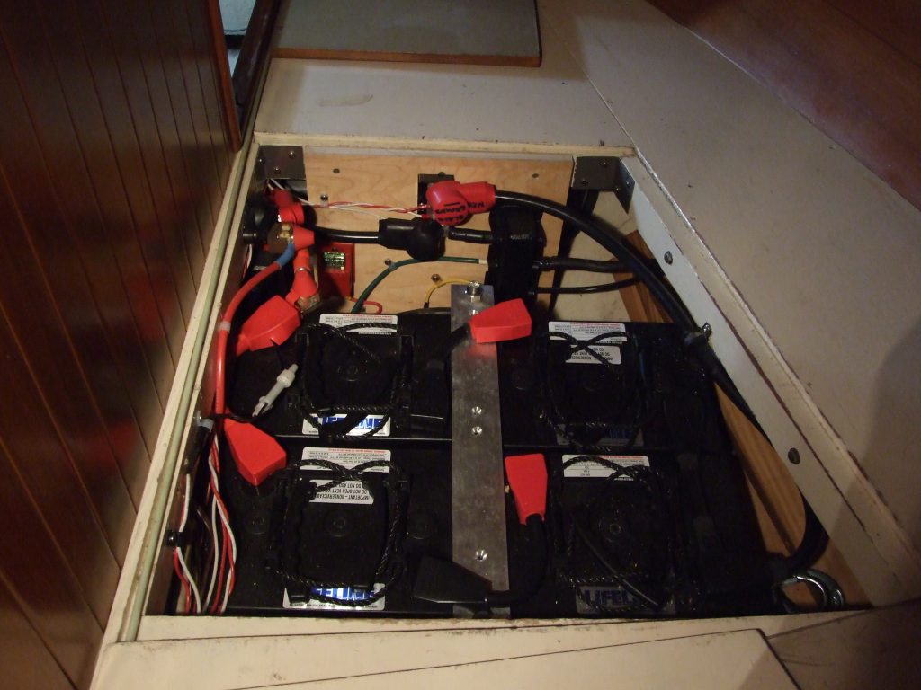
BATTERIES: When we got the boat it was equipped with two very large & very heavy 4D wet cell batteries. We learned on our first cruise that the 220 amp hours they produced were woefully inadequate for the power being consumed. We quickly installed a solar panel which helped in replacing some of the amps used. We then replaced all lighting with LED bulbs to reduce consumption. The biggest change, however, came when we replaced the two 4Ds with four, 6 volt, 220 amp AGM batteries. When a pair was wired in series, they became 12 volt & 220 amp hours. When each pair was then paralleled, they became our house bank of 12 volt & 440 amp hours. With the fridge going 24 hours a day, interior & exterior lighting, electric pumps, & even the inverter on so we can watch a movie, we have rarely dropped below 75% of capacity & we are usually no lower than 87%. Some of the advantages of the AGM batteries are that they are relatively light, they are maintenance-free, & they charge quicker. I then installed two large buss bars for the positive & negative feeds from this bank as well as the negative feed from the 12 volt, AGM starter battery which we also installed. All other wires & cables go from these buss bars. We installed a Link Pro battery monitor to see what the batteries are doing & we installed a series regulator that switches the charging so that, when the house bank is fully charged, the charging then goes to the starting battery. This has proven to be a nice, clean & dependable system.
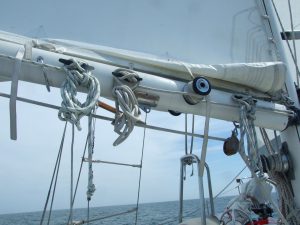
REEFING: The boom & the mainsail were fitted for two reefing points. When we had a new mainsail made, we wanted three reefing points (like shifting gears as the wind gets stronger). The inside of the boom could only accommodate the first two reefs, however, so we installed hardware on the outside of the boom for the third reefing line. This hardware included an eye strap with a ferrule on the port side to which is tied one end of the reefing line before it goes up to a cringle on the sail, a cheek block on the starboard side which turns the reefing line towards the mast, three more eye straps to keep the line from sagging & a cleat for tying off the other end of the reefing line. One winch is used for each of the three reefing lines. At various times, we’ve used any of the three points for wind strength as well as helm balance. Often times we just put one reef in for better balance & with a triple reef & the staysail we’ve happily sailed in 35 knots of wind (well, I’ve happily sailed – Nicole not so much). Nice to have a greater range of gears to shift depending on the conditions.
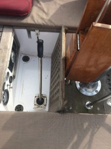
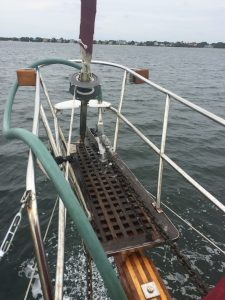
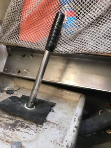
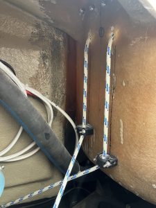
COCKPIT BILGE PUMP: Kalyra has an electric bilge pump, an automatic electric bilge pump (which we installed) & a manual bilge pump in the cabin under the floorboards at the base of the mast. We wanted another manual pump located in the cockpit that wouldn’t interfere with the helmsman but that the helmsman could also use while steering if necessary. Another concern for the location of the pump was that it did not interfere with any work needed under the cockpit (I have spent a lot of time down there).
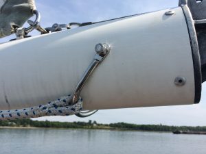
We installed this pump in the port side of the cockpit floor forward of the binnacle post. As the cockpit floor is so thick, some routing underneath was necessary to reduce the thickness where the pump was going to go (a very messy, noisy & dangerous job – necessary but I don’t recommend it). We also routed out a little of the cockpit teak grate to accommodate the top of the pump. The 1 1/2” discharge hose follows the underside of the cockpit & exits through a Marelon thru-hull located at the aft end of the boat about 4” below the caprail. The handles supplied with these pumps are very short, so we had our stainless steel guy fabricate a long, more robust handle that would allow the pumper to sit comfortably upright while working.
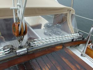
WASHDOWN PUMP: In the “credit where credit is due” department, the previous owner (who was also the first owner) installed a heavy duty pump under the floorboards near the mast. The intake for this pump was an 1 ½” hose to a seacock. The output was 1 1/2” hose connected to a length of 1 1/2” PVC pipe going up to the bow, then another hose that connects to a deck fitting on the port side, near the stem. A length of hose above is connected to this fitting & permanently resides on deck. When we up anchor, the hose is pushed onto a stainless steel piece of tubing which is permanently fixed above the anchor roller & is crimped to increase the pressure of the water that exits. When the pump is activated the water blasts the anchor chain as it’s coming in. This is like dragging your chain through a car wash & it’s hands free! Thanks Rich!
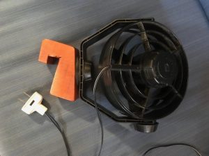
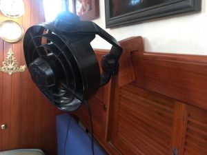
MOVEABLE FAN: Our first cruise on Kalyra started with an overnight sail to Block Island where we dropped anchor. There were three other Tayana 37s there & we got to know them all. During a tour of one of the boats (s/v Tranquillity, owners Rich & Mary), Rich showed us a clever way of having a moveable fan. Taking advantage of a finger rail that runs throughout the cabin at shoulder height, he had cut a piece of wood that would hook over this finger rail. He then got a 12v fan which was then attached to the wood & he installed a two-prong plug on the wire (the Tayana 37s have 12v, two-prong outlets as well as the 110v, three-prong outlets). This now becomes a portable fan that can be hooked & plugged-in anywhere in the boat. Being inexpensive & quick, this was one our first boat projects. A great addition.
Thanks Rich (a different Rich) & Mary!
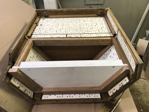
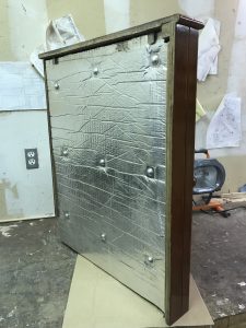
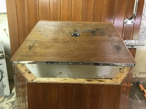
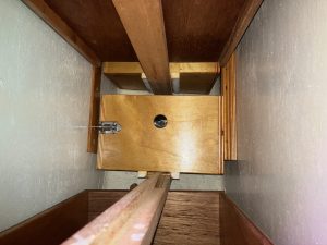
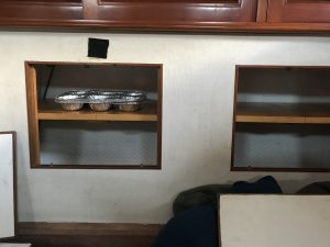
STEP STORAGE: For about eight years I kept thinking of the dead space within the forward engine cover (which is also a step into the cabin). Obviously it wasn’t a priority, but I finally did something about this. I installed ledgers on the engine cover for a back & a bottom. I then installed a primed plywood bottom. I removed the screws holding the step. Using a Fein multimaster tool, I carefully cut through the glue that was also holding the step. I then used the multimaster to cut the step 3/4″ from the riser. I installed a piano hinge & a nylon, friction catch for the step. As a final step, I screwed down a primed plywood back & installed soundproofing over that. The Tayana 37s have never lacked for storage but this was a no-brainer for a readily available space for rags, cleaners, etc. (light stuff only as you do have to lift off the engine cover regularly).
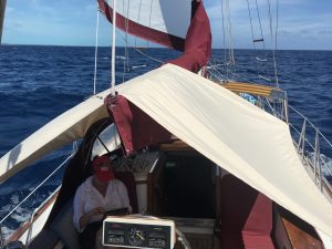
SMALL AWNING: We don’t have a bimini so we wear wide-brimmed straw hats instead. However, the sun in the Caribbean & the Bahamas was very intense & we found that we needed to get to some shade regularly. Enter Innovative Nicole. She experimented with a bedsheet thrown over the boom tying the two, aft corners to the pushpit & the two, forward corners to the gallows supports. This worked so well that we had a sunbrella awning made for us (the canvas maker in the Dominican Republic was so inexpensive & fast that we gave him the job). Grommets & bungee cords were affixed to the four corners. This awning has several advantages: It is very quick & easy to set-up or strike. It is small so it’s easy to stow. BUT, the greatest advantage that this awning has is that it can be used while underway. It’s thrown over the boom when doing jib-only runs (we had months of those in the Caribbean & the Bahamas). When using the mainsail, we simply tie a line between the backstay & the boom gallows & throw the awning over that. We love our big awning, but it can’t be used underway & it takes quite a bit more time to set up. This small awning fills those gaps perfectly. Plus, it makes for a great rain catcher for drinking water!
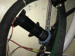
HOLDING TANK PUMP-OUT: Our boat came with a complicated & far less than ideal pump-out system for the holding tank. The holding tank is a molded fiberglass tank under the engine. A “T” fitting on top of the tank allows for two types of pump-out: A relatively short hose run up to a deck fitting near the cockpit (for pump-out services) & a very long run of hose going forward (under the cabin floor) to a manual pump next to the mast compression post and continuing on to a seacock in a starboard locker. This long run is further complicated by several 90 degree bends & it is even more complicated by the fact that this pump is a dual-purpose pump which can also be used to pump out the bilge. This dual-purpose function means that, aside from the more hose & fittings required, there were also valves which had to be turned on or off depending on which function you wanted. We ripped out all the hose, fittings & valves and replaced it with a single hose that goes straight to the bilge so that the manual pump is for the bilge only. One outlet of the “T” fitting on top of the tank was plugged. The hose outlet hose that was going up to the deck fitting was cut about half-way up & a “Y” valve was installed in this hose.
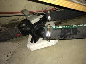

A Whale waste pump was installed under the starboard lazarette shelf (I have now used up all of this dead space) & a short hose ran between this and the “Y” valve. A slot was cut into the lazarette shelf for the pump handle. The output from this pump went through a very short hose to a seacock (this seacock was installed in an enlarged hole where there had been a smaller vent for the lazarette that I replaced with a mesh bag). We now have a very short & uncomplicated holding tank pump-out system.
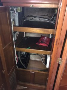
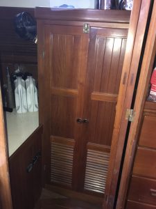
AFT LOCKER: There were two problems with this. First; the right door of the double doors hit the folded door of the aft cabin, so it could only open 45 degrees. We solved this by eliminating the right door hinges & hinging the two doors together – making a bifold door that allows full access to the locker. The second problem was that this was a hanging locker. We already had a wide hanging locker plus a hanging wet locker – how much hanging space do you need??! So we installed two shelves in this locker for whatever (sewing gear, crew gear, bedsheets, etc.). I had also installed a removable “wall” at the bottom so that this could also be used for storing gear (otherwise, the curvature of the hull at the bottom of this locker would cause anything put here to slide out). I also installed a lot of electronics on the sides of that locker (solar & windgen controllers, AIS, pactor modem, invertor, SSB black box, etc.).
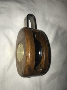
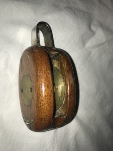
WOODEN BLOCKS: I love the look of wooden blocks and Kalyra has two doubles & four singles for her mainsheet – Beautiful to look at, but……….. As the years went by, the increased friction began to get annoying. The sheaves on these blocks had cylinder bearings. Wear & tear, etc. caused these sheaves to wiggle on the axle adding considerably to the friction already inherent in a cylinder bearing. I looked about to replace the sheaves with a much-better design. Enter Zephyrwerks. Not only did they replace the sheaves (these are now Delrin), but they also replaced axles where needed, did a whole rebuild & coated them with 10 coats of varnish. The difference is night & day (though you might not know this from the picture). Smooth, easy movement. No wiggling. Friction GREATLY reduced. And they even look better!
SHELVING/STORAGE: The storage spaces on our boat are remarkable, but anyone can always find more.
1) I installed a simple plywood shelf in the double-door, hanging locker. As this was “dead space” against the inner curvature of the hull, this shelf allowed for the storage of our large awning & side panels without interfering with the more-forward hanging items.
2) A fellow Tayana 37 owner gave me his technique for dealing with the “dead space” between the backs of drawers & the hull curvature. We have four drawers in our forward cabin. Because of the hull curvature & the short distance to the opposing wall, the drawers are shorter than the total depth of the opening for the upper two drawers. I fabricated two “inner drawers” out of 1/2″ plywood (angled to maximize storage). I attached two runners to the bottoms, drilled a finger hole & installed a barrel bolt to secure them after they were slid in. These provide great storage for lots of items that are rarely needed but will be needed sometime.


3) There are six storage compartments in the saloon that are behind the back cushions of the settees – three on each side. The port side compartments are filled with tool bags, caulking tubes, large tools, extra line, dinghy sail, etc. Two on the starboard side, however, are filled with canned, boxed & bagged foodstuffs. As these are relatively small, you would have to dig through a pile & pull things out until you would find the item you were looking for (which is usually on the bottom). To rectify this issue, I installed a shelf in each of these compartments. Not only is it easier to get what you’re looking for but it increases the usable storage space also.
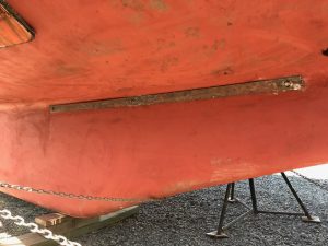
GROUNDING PLATE: As anyone should be, when you’re out in the ocean with a big stick (mast) pointing up at the sky, you need to be a bit conscious of lightning. Reading about this, however, can make your head explode with the differing opinions & solutions designed to make you & your boat relatively safe (no boat is 100% safe from lightning). A common thread though, was that one should have an easy way for lightning to exit the boat if you get hit, so this was the route I took.
After VERY CAREFUL measuring, we bolted a 2″x 72″x 3/16″ copper plate on the exterior hull where the keel starts to turn. The bolts were 1/2″ bronze & the middle one was fitted with a split nut. This nut connected one end of a 4/0 cable which was gently curved up the compression post and up into the aluminum mast to which the other end was bolted about 8″ up from the deck (we have a deck stepped mast). At the top of the mast, I installed a 1/2″ round x 40″ aluminum aerial that is about 7″ taller than anything else up there. The chainplates as well as our steel tanks are also connected to this grounding plate.
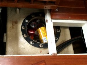
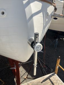
CAPE HORN WINDVANE: Our boat has an autopilot for self-steering and this is great, but it requires electricity. Self-steering is very important (indeed necessary) on long passages with a shorthanded crew. As 99% of the time, only Nicole & I are aboard, we wanted a back-up system and the Cape Horn windvane was it. We went with this solution because: No electricity is required. The connections are all inside the boat so there is a bare minimum amount of the system that is mounted on the stern vs having an “oil derrick” following you. Because the connections are inside where they connect directly with the rudder post, there are no lines cutting across the cockpit to attach to the wheel.
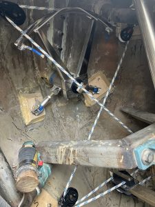
The installation of this windvane on our boat, however, was a bit daunting. For a boat with our displacement, a 3 5/8″ hole has to be drilled through the transom about 28″ up from the waters edge. This hole is for a 3 1/2″ stern tube which must be level. After double-checking my measurements a few hundred times, I put the order in (they are all custom-made). To be fair, the website & the installation manual were great as was the fact that Yves, the designer, and Eric always made themselves available to answer any questions via email or phone. The anxiety I was experiencing was because of our specific boat, ie: 1) There were two rudder post supports, the engine exhaust hose & a bilge pump hose that reduced the area that the Cape Horn quadrant could rotate in to having a 1/2″ maximum allowance for error, and 2) The fiberglass of our transom is 1 1/4″ thick and half of the hole that has to be drilled through this will also have to go through 3 1/2″ of a fiberglass knee (for the backstay), and, finally, 3) Drilling a 3 5/8″ hole into your boat is a scary thing!
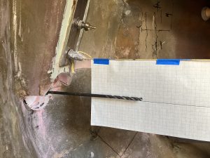
Just before the boat was hauled out, I adhered a level string between the backstay chainplate & the center of the rudder post. Once on land, the yard crew worked with me to adjust the boat until this string was again level. After determining the center of the hole, I drilled a 1/4″ pilot hole. Using a second level, I measured the distance down from the string, marked this as a line drawn onto graph paper, & taped this paper to the string. Using an 18″ long 1/4″ drill bit as the pilot bit for my 3 5/8″ hole saw, I was drilling from outside while Nicole was down in the stern watching the long bit in relation to the line on the paper. In this way, she could direct me as to which way I should go as I was drilling.
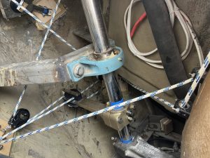
I then cut, drilled & attached two adjustable support legs between the horizontal tube & two plywood pads that I had epoxied inside the hull. I then epoxied and caulked the tube.
Next I installed the horizontal axis into the horizontal tube & bolted the windvane quadrant onto the inside end of this horizontal axis.
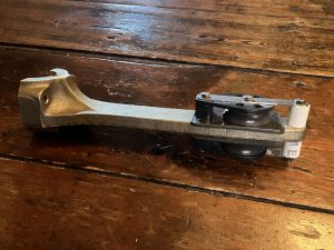
The best connection point between the windvane & the rudder post was a rear-facing tiller arm that would clamp around & bolt onto the post. Because of the space requirements, I opted to bolt two cheek blocks to this arm (rather than shackling a single block on each side of the arm which would have greatly increased the effective width).
The rivets holding the sheaves & the line retainers were drilled out, two stainless steel straps were cut & drilled and two line retainers were made from PVC.
The line (which is continuous – starting & ending on opposite ends of the Cape Horn quadrant) was then brought up through fairleads to two holes that I drilled into the fiberglass of the cockpit (on the centerline & a few inches below the helmsman’s seat) and lined up with two cam cleats that I had bolted in place.
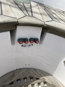
When deployed, this slack line is pulled up tight & cleated with the cam cleats.
The windvane mast was then installed onto the horizontal axis & was supported by two adjustable stainless steel tubes which were bolted to the mast and screwed to the caprail. The steering oar was hung by a bungy cord & snapped onto two pins on the downward facing tube of the horizontal axis. The crescent was then attached to the top of the mast & the vane was bolted to this.
When the steering oar is being used, it hangs straight down into the water. When it’s not being used & it’s undesirable to have it in the water. it can be swung up sideways & lashed to the CH mast (or, in our case, to the davits).
The first several days of using this windvane were remarkable, but there were certain bugs that had to be worked out (mostly operator error). Unfortunately, I had finished this installation shortly before we were crossing the Atlantic & the conditions we had throughout most of the leg from NY to the Azores were not conducive to adjusting this gear. When we got to the Azores, though, I was able to work this out & it is a great self-steering system.
shower rod
stern pulpit
shelves under stove
fuel lines
ratlines
stays/shrouds/himod
propane conversion
anchor roller
Recent Comments